
| 일 | 월 | 화 | 수 | 목 | 금 | 토 |
|---|---|---|---|---|---|---|
| 1 | 2 | 3 | 4 | 5 | 6 | |
| 7 | 8 | 9 | 10 | 11 | 12 | 13 |
| 14 | 15 | 16 | 17 | 18 | 19 | 20 |
| 21 | 22 | 23 | 24 | 25 | 26 | 27 |
| 28 | 29 | 30 |
- Crestron
- Conference Room AV
- Meeting Room Automation
- LAN Control
- Crestron NVX
- Wireless HDMI
- Video Conferencing
- AV System Integration
- AirMedia
- Cresnet
- DM NUX
- Control Subnet
- Video Wall
- Crestron Korea
- Teams Rooms
- Integrated Control
- IR Serial
- Zoom Rooms
- AV over IP
- Crestron CP4N
- DM-NVX-384
- Meeting Room AV
- Relay Wiring
- Hybrid Meeting
- BYOM
- AM-TX3-200
- AV-over-IP
- Crestron CP4
- AV SI
- Versiport
- Today
- Total
RAQIA | Crestron Solutions in S.Korea
Crestron CP4N Wiring Guide: Relay, I/O, IR, Cresnet, and Control Subnet 본문
Crestron CP4N Wiring Guide: Relay, I/O, IR, Cresnet, and Control Subnet
RAQIA 라키아 2026. 5. 19. 14:13Crestron CP4N Wiring Guide: Relay, I/O, IR, Cresnet, and Control Subnet
Hello, this is RAQIA.
In a previous article, we reviewed the basic communication methods used in integrated control systems, including RS-232, RS-485, and LAN control.
Today, we will focus on the physical wiring side of the Crestron CP4N.
In real AV SI and integrated control projects, many questions are not about software first. They are about physical connection:
- Which port should be used for motorized blinds?
- How should relay outputs be wired?
- What can I/O ports detect?
- When should IR-Serial outputs be used?
- What is Cresnet?
- What is the Control Subnet port on CP4N?
- Can Control Subnet be connected to a normal company LAN?
These questions matter because incorrect wiring can cause system instability, device malfunction, or network conflicts.
In this guide, we will explain the major CP4N physical control ports: Relay, I/O, IR-Serial, Cresnet, LAN, and Control Subnet. We will also discuss practical wiring concepts for devices such as motorized blinds, projection screens, sensors, displays, and Crestron network devices.
CP4 vs CP4N: What Is the Difference?
The Crestron CP4 and CP4N are both professional control processors used for integrated control systems.
They share many of the same physical control interfaces, including relay outputs, I/O ports, IR-Serial outputs, COM ports, and LAN control.
The key difference is that CP4N includes a dedicated Control Subnet port.
Control Subnet is designed to create a dedicated Crestron device network separated from the main corporate LAN. This can help improve stability, simplify Crestron device communication, and reduce unnecessary interaction with the general IT network.
In simple terms:
- CP4: Professional Crestron control processor
- CP4N: CP4 with an additional dedicated Control Subnet port


For larger AV SI projects, meeting rooms, smart offices, and DM NVX environments, the Control Subnet port can be very useful when designed correctly.
CP4N Port Overview
The Crestron CP4N includes multiple physical control ports for different types of devices.
| Port Type | Main Purpose | Typical Use |
|---|---|---|
| Relay Output | Dry contact control | Motorized screens, blinds, simple switching |
| I/O Versiport | Digital input/output and analog input | Sensors, triggers, state detection |
| IR-Serial Output | IR control or one-way serial output | TVs, set-top boxes, legacy AV devices |
| NET / Cresnet | Crestron bus communication and power | Crestron keypads, sensors, Cresnet devices |
| LAN | Corporate network connection | IP control, remote management, network AV |
| Control Subnet | Dedicated Crestron device network | TSW touch panels, DM NVX endpoints, Crestron devices |
Each port has a different purpose. A professional control system should map the correct device to the correct port during the design stage.
Relay Output: Dry Contact Control for Physical Devices
Relay outputs are used for simple contact closure control.
They are not used for data communication. Instead, they open and close an electrical contact to trigger a device or circuit.
Relay outputs are commonly used for:
- Motorized projection screens
- Motorized blinds
- Simple lighting control
- Lift or elevator call interfaces
- Door release interfaces
- Power sequencer trigger inputs
- Dry contact control devices
In a meeting room, a relay output may be used to lower a projection screen when “Presentation Mode” is selected.
In a smart office, relay outputs may be used to control blinds, screens, or simple contact-based equipment.
The important point is that relay outputs are simple and reliable, but they must be used within their electrical rating. If the connected load is too large, an external relay or contactor should be used instead of connecting the load directly to the CP4N.
Relay Wiring for Motorized Blinds
Motorized blinds and screens are common devices in Crestron integrated control projects.
Depending on the product, the blind controller or receiver may provide dry contact inputs for commands such as:
- Up
- Down
- Stop
In that type of system, CP4N relay outputs can be used to simulate button contact closure.
A typical design may use separate relay outputs for each command.
For example:
- Relay 1: Up command
- Relay 2: Down command
- Relay 3: Stop command
The exact wiring depends on the blind receiver or controller. The integrator should always check the wiring manual of the motorized blind system before connection.
Somfy RTS Receiver and CP4N Relay Wiring Concept
Somfy RTS receivers are often used for motorized blind control.

In some configurations, an RTS receiver may provide external dry contact input terminals for commands such as up, down, or stop.
When connecting a Crestron relay output to this type of receiver, the most important concept is the common reference connection.
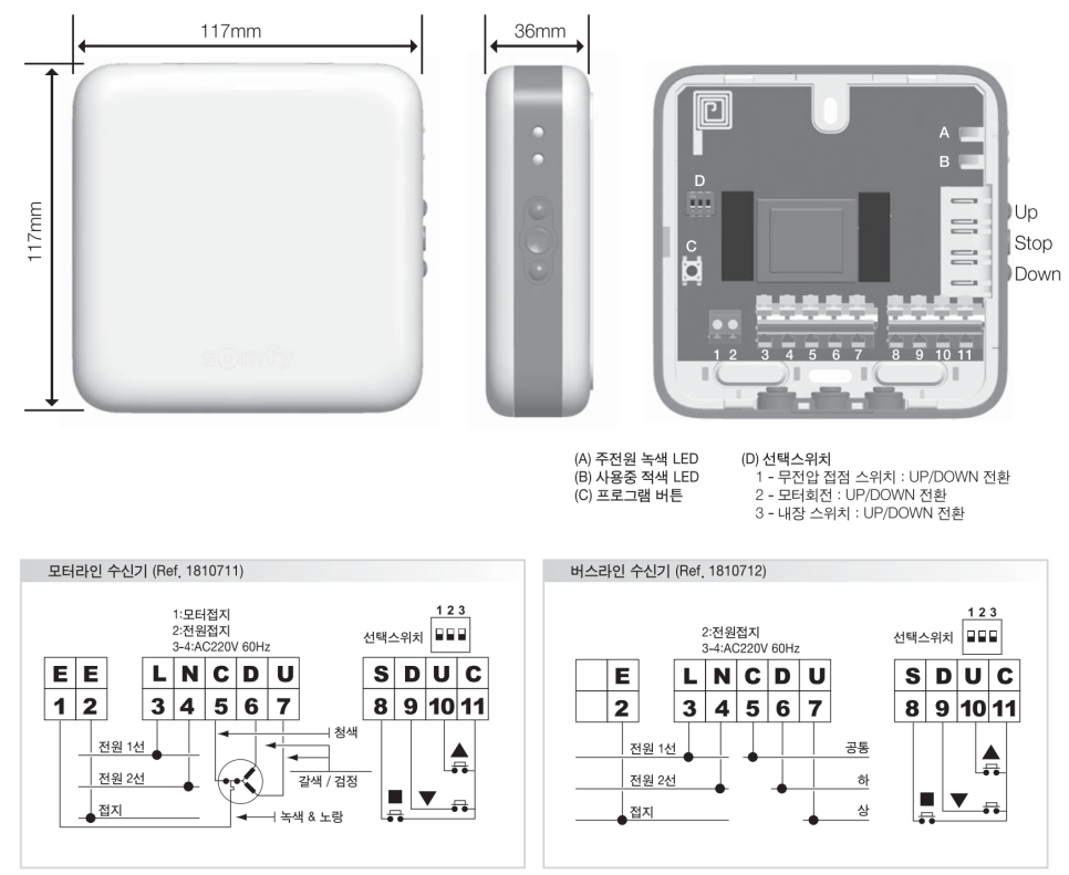
In practical terms, the common ground or common terminal of the receiver should be connected properly with the relay common path so that the contact signal is recognized correctly.
If the common reference is not wired correctly, the signal may float, the receiver may not detect the command, or the blind may behave unpredictably.
For this reason, motorized blind wiring should always be tested carefully before final installation.
Important points include:
- Check the receiver’s dry contact input diagram
- Confirm which terminal is common
- Use separate relay outputs for up, down, and stop if required
- Do not exceed the relay electrical rating
- Test each command before closing the wall or rack
- Document the wiring clearly for future maintenance
Small wiring mistakes in blind control can lead to difficult troubleshooting later, especially when equipment is hidden inside ceilings, walls, or furniture.
I/O Versiport: Sensor Input and Logic Control
The CP4N includes I/O ports often referred to as Versiports.
These ports can be used for digital input, digital output, or analog input depending on system programming and wiring design.
I/O ports are commonly used with:
- Motion sensors
- Door sensors
- Occupancy sensors
- Temperature sensors
- Contact sensors
- Simple trigger devices
- Logic-level signals
For example, in a smart meeting room, an occupancy sensor may be connected to an I/O input. When a person enters the room, the system can wake up the touch panel, turn on the display, or prepare the room environment.
I/O ports can also be used for simple output triggers depending on the device requirements.
Because I/O ports can operate in different modes, the integrator must confirm the electrical requirements of the connected device before wiring.
Analog Input with I/O Ports
Some sensors provide analog voltage signals rather than simple on/off contact signals.
In those cases, an I/O port configured as an analog input may be used.
Analog input may be useful for:
- Light level sensors
- Temperature sensors
- Environmental sensors
- Variable voltage signals
For example, a light sensor may provide a voltage value that represents brightness. The control system can read this value and adjust lighting or shades automatically.
This can support more advanced smart office or premium residential automation scenarios.
IR-Serial Output: Controlling Legacy Devices
The CP4N provides IR-Serial outputs that can be used either for infrared control or one-way serial output depending on the programming and wiring.
IR control is commonly used for devices that do not provide better control interfaces.
Typical IR-controlled devices include:
- Consumer TVs
- Set-top boxes
- Blu-ray players
- Media players
- Some projectors
In IR control, an IR emitter is attached near the device’s IR receiver window. The CP4N sends IR commands through the emitter, similar to a remote controller.
IR is useful for legacy or consumer devices, but it is usually less reliable than RS-232 or LAN control because it depends on emitter placement and device response.
For professional meeting rooms, RS-232 or network control is preferred when available.
One-Way Serial Output
Some IR-Serial ports can also be used for one-way serial-style output.
This may be useful for devices that only need commands sent to them and do not return feedback.
Examples may include:
- Simple signage devices
- Lighting drivers
- Basic control modules
- Devices requiring only command transmission
However, one-way serial control cannot receive status feedback from the controlled device.
If the system needs feedback, confirmation, or two-way communication, a COM port or LAN control method should be used instead.
NET / Cresnet: Crestron Bus Communication
Cresnet is Crestron’s proprietary network used to connect compatible Crestron devices.
It carries both communication and power over a dedicated wiring structure.
Cresnet is commonly used for:
- Crestron keypads
- Wall controls
- Some sensors
- Lighting control devices
- Cresnet-compatible accessories
In many Crestron systems, Cresnet functions as a reliable control bus for Crestron devices.
When designing Cresnet wiring, the integrator should consider:
- Total power consumption
- Cable length
- Voltage drop
- Device count
- Proper Cresnet wiring polarity
- Use of additional Cresnet power supplies if needed
Because Cresnet can provide power to connected devices, power budget calculation is important.
Cresnet Power Considerations
Cresnet wiring is not only about data. It also involves power delivery.
If too many devices are connected or the cable distance is too long, voltage drop can become a problem.


Possible symptoms include:
- Keypads not responding
- Devices rebooting
- Unstable communication
- Intermittent device errors
For larger systems, additional Cresnet power supplies or different wiring topology may be required.
This should be reviewed during system design, not after installation.
LAN Port: Main Network Connection
The CP4N includes a LAN port for the main network connection.
This port is typically connected to the corporate network or AV network depending on the system design.
The LAN port may be used for:
- IP device control
- Remote programming
- System monitoring
- Network-based AV device communication
- Touch panel communication depending on architecture
- Integration with IT-managed environments
Because LAN control connects the control processor to a network, IT coordination is important.
Important network design points include:
- IP address plan
- Subnet configuration
- VLAN policy
- Firewall rules
- Device authentication
- Remote access policy
- Network security
For enterprise meeting rooms, Teams Rooms, Zoom Rooms, and smart offices, AV and IT network planning should be coordinated carefully.
Control Subnet: Dedicated Crestron Device Network
The Control Subnet port is one of the most important differences between CP4 and CP4N.
Control Subnet is designed to provide a dedicated network for Crestron Ethernet devices.
This can be useful when connecting devices such as:
- Crestron touch panels
- DM NVX endpoints
- AirMedia devices
- Crestron network accessories
- Other Crestron Ethernet devices
The main idea is to separate Crestron device traffic from the main corporate LAN.
This can help reduce network conflicts, simplify device discovery, and improve system reliability when designed correctly.
Control Subnet may also support functions such as DHCP and DNS services for connected Crestron devices, depending on configuration.
Important Warning: Do Not Treat Control Subnet Like Normal LAN
The Control Subnet port should not be treated like a normal company LAN port.
It is intended for Crestron device networking, not general internet access or ordinary office network expansion.
Incorrectly connecting Control Subnet to the corporate LAN or to the wrong network switch may cause:
- IP conflicts
- DHCP conflicts
- Device discovery issues
- System instability
- Network troubleshooting problems
This is one of the most important field mistakes to avoid.
Before connecting anything to Control Subnet, the integrator should confirm the network architecture and Crestron device plan.
How CP4N Supports One-Touch Meeting Room Automation
The physical wiring of CP4N becomes meaningful when it supports real user scenarios.
For example, a “Start Meeting” button on a Crestron touch panel may trigger:
- Display power on through RS-232 or LAN
- Input selection for Teams Rooms or Zoom Rooms
- Audio DSP preset recall
- Motorized blinds lowering through relay control
- Lighting scene activation
- Camera preset selection
- Wireless presentation readiness
- Room occupancy logic based on I/O sensors
To the user, this looks like one simple button.
Behind that button, CP4N may communicate through LAN, relay, I/O, IR, Cresnet, and other control interfaces at the same time.
This is the value of professional integrated control.
CP4N in AV SI, Teams Rooms, and Zoom Rooms Projects
Microsoft Teams Rooms and Zoom Rooms are often installed as video conferencing platforms.
However, the room experience usually requires more than the meeting platform itself.
A complete room may need:
- Display control
- Audio system control
- Camera presets
- Lighting scenes
- Blind control
- Wireless presentation
- Occupancy-based automation
- Room shutdown logic
- Remote support and monitoring
This is where CP4N can become part of a broader AV SI and integrated control design.
A Teams Rooms or Zoom Rooms installation should not only be a camera and display installation. In premium meeting rooms, it should be designed as a complete room automation system.
Common Wiring Mistakes in CP4N Projects
Here are common field mistakes to avoid.
1. Exceeding Relay Ratings
Relay outputs should not directly switch loads beyond their electrical rating. Use external relays or contactors when needed.
2. Not Sharing the Correct Common Reference
For dry contact control, the common or ground reference must be wired correctly depending on the controlled device.
3. Using IR When RS-232 or LAN Is Available
IR can work, but RS-232 or LAN is usually more reliable for professional AV systems.
4. Ignoring Cresnet Power Budget
Cresnet devices consume power. Too many devices or long cable runs can cause voltage drop and instability.
5. Connecting Control Subnet to the Wrong Network
Control Subnet should be used for Crestron device networking. It should not be casually connected to the general office LAN.
6. Poor Documentation
Relay numbers, I/O assignments, Cresnet device IDs, and network addresses should be documented clearly for future maintenance.
Practical Design Checklist
Before installing CP4N in an AV SI or integrated control project, review this checklist.
- Which devices require relay control?
- Do any loads exceed the CP4N relay rating?
- Which sensors connect to I/O ports?
- Are analog inputs required?
- Which legacy devices require IR control?
- Which devices need two-way serial control instead of one-way IR-Serial?
- Are Cresnet devices included?
- Is the Cresnet power budget sufficient?
- Which devices should be on LAN?
- Which Crestron devices should be on Control Subnet?
- Is the Control Subnet isolated correctly?
- Is wiring documentation prepared?
- Has the system been tested before final handover?
This checklist can reduce many common installation problems.
RAQIA: Crestron CP4N Integrated Control and AV SI in Korea
RAQIA is a premium integrated control and AV system brand operated by Bizware System Co., Ltd. in South Korea.
RAQIA specializes in AV SI, Crestron-based integrated control, meeting room automation, Microsoft Teams Rooms, Zoom Rooms, AV-over-IP systems, DM NVX, display control, lighting control, blind control, smart office integration, and premium space automation.
For companies considering Crestron CP4N, Control Subnet, Cresnet, relay wiring, meeting room automation, Teams Rooms, Zoom Rooms, or smart office integrated control, RAQIA can help design the complete control architecture from physical wiring to touch panel UI.
Official RAQIA service pages:
- Crestron Integration and Silver Partner
- AV System Integration
- Video Conferencing Integration
- Contact RAQIA
Conclusion: CP4N Wiring Is the Foundation of Reliable Integrated Control
Crestron CP4N is a powerful control processor, but reliable operation depends on correct wiring and system design.
Relay, I/O, IR-Serial, Cresnet, LAN, and Control Subnet each have different roles.
When these ports are planned correctly, CP4N can support one-touch meeting room automation, display control, blind control, lighting scenes, Teams Rooms workflows, Zoom Rooms workflows, and smart office integration.
When they are wired incorrectly, even a simple room control function can become unstable.
For professional AV SI and integrated control projects, physical wiring should be treated as a core part of the system architecture.
The best control system is not only about programming.
It starts with correct wiring, clear documentation, and a design that matches the real room workflow.
FAQ
What is the difference between Crestron CP4 and CP4N?
CP4 and CP4N share many control capabilities, but CP4N includes a dedicated Control Subnet port for Crestron device networking.
What are CP4N relay outputs used for?
Relay outputs are used for dry contact control, such as motorized screens, blinds, simple lighting triggers, contact closure devices, and physical ON/OFF control.
What is Cresnet used for?
Cresnet is Crestron’s proprietary bus system used to connect compatible Crestron devices such as keypads, sensors, and control accessories while providing communication and power.
Can Control Subnet be connected to a normal LAN?
Control Subnet should not be treated as a normal office LAN connection. It is intended for Crestron device networking and should be designed carefully to avoid network conflicts.
Why is CP4N useful for Teams Rooms and Zoom Rooms?
CP4N can support the broader room control layer around Teams Rooms or Zoom Rooms, including display control, lighting scenes, blind control, camera presets, AV routing, and one-touch meeting automation.
For Crestron CP4N, AV SI, integrated control, and Teams Rooms planning in Korea:
- Official Website: https://www.raqia.co.kr/
- Crestron Integration: https://www.raqia.co.kr/crestron-silver-partner
- AV System Integration: https://www.raqia.co.kr/solution-service/videoaudio
- Video Conferencing Integration: https://www.raqia.co.kr/solution-service/videoconference
- Demo Room Reservation: Contact RAQIA
- Email: jhwh@raqia.co.kr
- Phone: 010-9508-6382 / +82-2-558-8347
When wiring is designed correctly, integrated control becomes stable.


